Truck Update 5/27/18

  • Received and fit checked waterjet aluminum adapter plates for roof hatch
  • Fit checked key blanks in truck
  • Deburred and paint prepped aluminum roof hatch adapter plates
  • Masked off bond areas on aluminum roof hatch adapter plates
  • Primed and painted aluminum roof hatch adapter plates
  • Disposed of scrap material from subframe
  • Started laying out wiring diagram
  • Started detail design of tire mount
  • Laid roof panel on floor to prepare for edge champher
  • Ordered habitat wiring
  • Fit checked fantastic fan in roof panel cutout
  • Champhered top edges of roof panel
  • Received habitat wiring order
  • Cut foam for core between aluminum hatch adapter plates
  • Prepped and bonded top roof hatch adapter plate
  • Routed top side of hatch opening
  • Flipped over roof panel
  • Champhered lower edges of roof panel
  • Prepped and bonded lower roof hatch adapter plate
  • Routed bottom side of hatch opening and removed excess composite panels

We encountered an unforeseen mix-up in the layout of our roof panel when we received the physical roof hatch from Tern Overland. It was a bit of a collaborative miss with everyone involved (us, Total Composites, and Tern Overland). When we originally laid out our roof panel, the orientation of the roof hatch was not obvious and we accidentally assumed that the hinge would be on the narrow side of the hatch like many American hatches. It was a bit of a surprise when we opened the box and read the instructions and found that our opening was rotated 90 degrees in our panel from what it needed to be.

We hadn’t actually specified dimensions of the hatch opening when we supplied the information for the box layout. We just specified the center position of the hatch and said that there needed to be an opening for the supplied roof hatch. We did, however, have a rectangle in the layout drawings that was longer fore-and-aft and narrower side-to-side. We had assumed that any needed details of the hatch layout would be double checked against the requirements of the hatch, but unfortunately, that did not happen.

The bottom line is that we should have requested the full installation instructions for the hatches, windows, and door prior to submitting our box layout for build. Also, it’s best to get instructions directly from manufacturers via email instead of relying on what is on websites as products and details online can change over time.

Roof Hatch Plan
Roof Hatch Plan

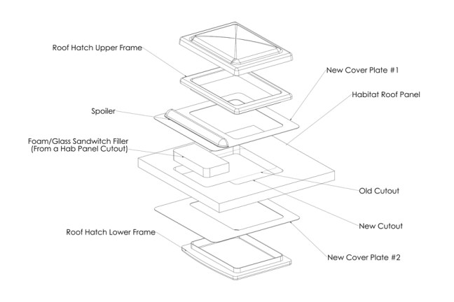
Overall, we have a pretty good recovery plan. We had 2 aluminum plates water jet cut that bond to the upper and lower surfaces of our habitat roof and act as “adapters” to rotate the orientation of the roof hatch cutout. The plates add minimal weight and actually reinforce the roof around the large roof hatch opening.

Roof Hatch Plan
Roof Hatch Plan

Truck Update 5/20/18

  • Received Sika 205 Activator
  • Re-cut fillets in forward panel for passthrough frame (we changed our passthrough design after Total Composites cut our panel)
  • Fit checked passthrough frames
  • Added required fillets to passthrough cutout corners
  • Bond prepped forward passthrough cutout
  • Prepped passthrough frames using Sika 205 activator
  • Bonded in passthrough frames using Korapop 225
  • Cut steel for back wall hardpoints
  • Painted rock shields

Truck Update 5/13/18

  • Fit checked forward wall panel again
  • Bond prepped and bonded forward wall
  • Trimmed scrap side wall panel for fixturing side wall extrusion bond
  • Fit checked and trimmed forward side wall extrusion
  • Marked and trimmed height of forward side wall extrusion
  • Bond prepped and bonded forward side wall extrusions
  • Clearance trimmed aft end of lower extrusions
  • Bond prepped and bonded driver side wall
  • Bond prepped and bonded passenger side wall

Truck Update 5/6/18

  • Started habitat assembly sequence planning
  • Sent out quote requests for water jet cutting aluminum roof hatch adapter plates (dedicated blog post about this topic to come in the future)
  • Inspected and touched up subframe paint
  • Laid habitat floor panel upside down on floor
  • Prepped habitat floor steel hardpoints for bonding
  • Dry fit hardpoints in floor
  • Rounded edges of hardpoint straps to ease foam installation
  • Bonded and installed hardpoints and foam in habitat floor panel
  • Drilled and tapped one central hole in each hardpoint to clamp
  • Re-positioned truck and habitat floor in shop for habitat assembly
  • Pilot drilled and tap drilled mount holes in habitat floor
  • Clearance drilled fiberglass at hardpoint holes
  • Tapped hardpoints in habitat floor
  • Reviewed bond primer requirements
  • Ordered Sika SP-205 (from EMI Supply) to prime aluminum to bond with Korapop 225.
  • Cut high density urethane foam blocks for floor support during habitat assembly
  • Bonded terry cloth to top of foam blocks with 3M 77
  • Removed clamps and temporary bolts from bonded hardpoints
  • Chamfered and cleaned lower edge of habitat floor panel
    • All panel edges had a lot of gel coat build up that needed to be removed and the edges needed to be softened. Previous fit checks show that this was a required step to get the panels to fit well in the extrusions.
  • Flipped, leveled, and positioned habitat floor panel
  • Chamfered and cleaned upper edge of habitat floor panel
  • Chamfered and cleaned all edges (including passthrough cutout) of forward panel
  • Rearranged panels and extrusions in shop space
  • Chamfered and cleaned all edges (including all cutouts) of left and right side panels
  • Dry fit checked all lower extrusions
  • Measured all panels and extrusions (again)
  • Checked flatness of floor on support blocks
  • Masked floor panel with heavy paper
  • Bond prepped and bonded forward lower extrusion using Korapur 140
  • Bonded several adhesive test samples using Korapur 140
  • Finalized order of water jet cut aluminum roof hatch adapter plates
  • Additional measurements and fit checking
  • Measured back wall panel height in preparation for cutting steel hardpoints
  • Bond prepped and bonded both side lower extrusions using Korapur 140

Truck Update 4/29/18

  • Removed fenders in preparation to paint subframe
  • Placed habitat floor panel on subframe
  • Match drilled all mounting holes through subframe into habitat floor
  • Made epoxy repair to small delaminated corner of habitat floor
  • Fit checked exhaust tubing downstream of muffler
  • Removed habitat floor panel from subframe
  • Finish welded exhaust and muffler
  • Continued subframe paint prep
  • Weld prepped subframe for spacer washers
  • Drilled all subframe to habitat bolt holes in frame rails
  • Welded spacer washers into place
  • Prepped and primed subframe
  • Received ignition key blanks
  • Painted subframe gloss black

Truck Update 4/22/18

  • Final installed cab inner passthrough frame
  • Ordered fender mount hardware
  • Disposed of old passenger bench seat
  • Cut square spacer washers for mid section of subframe under floor
  • Drilled oversized holes in spacer washers
  • Painted kitchen cabinet / pantry gloss white
  • Measured dimensions to make rock shield for top of rear fenders
  • Started laying out new position for muffler assembly
  • Started kitting muffler assembly parts
  • Ordered SBU OEM ignition key blanks from Expedition Imports
  • Welded muffler in new position
  • Removed aft under bed box mounts and jerry can mount in preparation for subframe painting
  • Fabricated exhaust and muffler mount brackets
  • Fabricated and match drilled rock shields for top of rear fenders
  • Welded on muffler bracket and bolted muffler mount bracket to old spare tire mount holes
  • Painted muffler mount
  • Removed driver side under bed storage mount in preparation for subframe painting

Truck Update 4/15/18

  • Received jerry cans
  • Received roof hatch from Tern Overland
  • Received new mechanical suspension cab seats
  • Updated roof hatch installation plan
  • Mocked up fender mounts
  • Mounted rear fenders to subframe
  • Started working to move muffler forward


Truck Update 4/8/18

  • Purchased steel for spare tire mount, subframe spacers, and back panel hardpoint inserts
  • Prepped, primed, and painted back wall of cab
  • Received drills and taps for subframe
  • Painted cab inner passthrough frame
  • Seam sealed all cab passthrough welds using Eastwood seam sealer
  • Applied second coat of paint on cab inner passthrough frame
  • Drilled 52 new 1/8″ diameter pilot holes in subframe
  • Final painted back wall of cab
  • Rearranged truck part storage area
  • Installed rear cab ceiling trim
  • Reinstalled rubber edge cover on back wall of cab
  • Removed cab headliner and inspected condition
  • Wiped down cab interior
  • Removed tail light brackets
  • Retorqued bolts that hold subframe to truck chassis (5 were so loose they could rotated by hand)
  • Moved tail lights aft to accommodate storage boxes
  • Relocated rear gladhands
  • Preliminary mounting of aft underbed storage
  • Prepped and painted back portion of truck frame

Truck Update 4/1/18

  • Started welding passthrough frame to cab
  • Received pintal clamp bolt
  • Received acoustic foam
  • Received roof rack cargo boxes
  • Received aluminum trim for passthrough cab interior
  • Finished passthrough structural welding on exterior of cab
  • Ordered jerry cans
  • Ordered seats for cab
  • Marked subframe to hab floor bolt hole locations on subframe rails
  • Started subframe paint prep
  • Finished passthrough tig welding inside cab
  • Finished structural welding of passthrough frame on cab
  • Removed and disposed of foam from inside roof rack cargo boxes
  • Cleaned shop and recycled scrap material
  • Received bellows from Uni-Grip
  • Sketched out plates to fill cab back windows
  • CAD modeled plates to fill cab back windows
  • A friend was nice enough to plasma cut the plates to fill cab back windows: AeroDesign
  • Another friend gave us some Lord 7545 adhesive to try on the bellows: Monolith Aeroworks
  • Applied second coat of paint to habitat passthrough frame
  • Cut aluminum for cab passthrough trim
  • Drilled and tapped mounting holes for cab passthrough trim in cab side steel passthrough frame
  • Machined aluminum spacer for rear pintal shear bolt
  • Trimmed passthrough door
  • Rounded corners of cab side steel passthrough frame
  • Purchased abrasive disc for removing scale from subframe
  • Purchased black silicone to seal removable frame on cab passthrough
  • Continued removing scale from subframe
  • Drilled and tapped holes in cab passthrough frame for removable forward passthrough frame
  • Tack welded plates over old window openings
  • Started touch up paint on back of cab

Truck Update 3/25/18

  • Received kitchen cabinet and locks
  • Received and fit checked 2 1/2″ rear pintal
  • Began truck cab passthrough cutout planning
  • Measured roof rack
  • Researched roof rack cargo box options
  • Started stripping down kitchen cabinet for repaint
  • Started laying out passthrough door
  • Purchased low profile deadbolt lock for passthrough door
  • Cut aluminum for the passthrough door edging
  • Ordered cargo boxes for roof rack
  • Started laying out passthrough door panel
  • Removed unneeded material from inside cab back wall
  • Removed old insulation from cab roof hatch (23 7/8″ diameter)
  • Removed rear cab windows
  • Marked passthrough cut out in back of cab
  • Laminated plywood for passthrough door panel
  • Trimmed down height of kitchen cabinet
  • Marked trim line on and trimmed forward passthrough frame
  • Cut passthrough opening in back of cab
  • Fit checked forward passthrough frame opening
  • Removed passenger seat and unneeded sheet metal
  • Removed rear pintal (42 pound assembly)
  • Bonded aluminum facesheets to passthrough door panel
  • Purchased masonite for new roof hatch insulation mount
  • Started looking for new cab seats
  • Ordered insulation/sound deadening for cab rear wall and roof hatch
  • Started tack welding passthrough frame to cab